
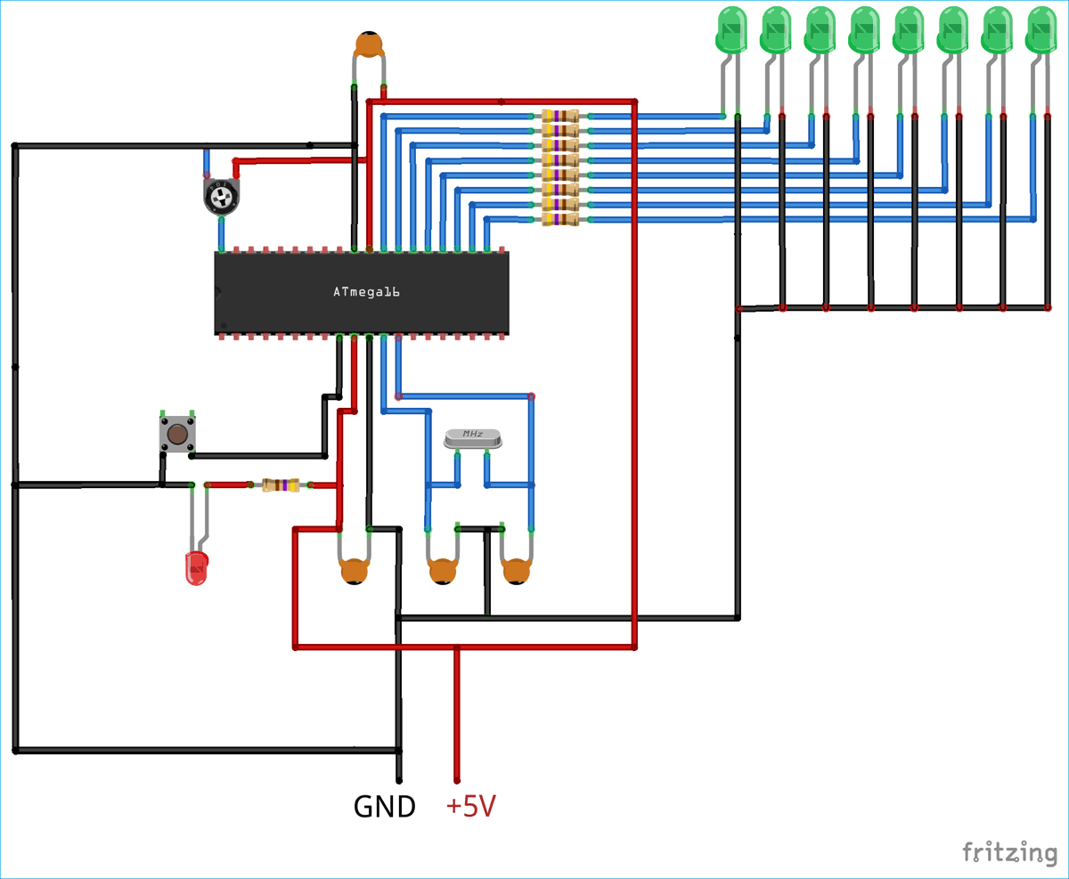
One common feature that is used in almost every embedded application is the ADC module (Analog to Digital Converter). These Analog to digital Converters can read voltage from analog sensors like Temperature sensor, Tilt sensor, Current sensor, Flex sensor etc. In this tutorial we will learn What is ADC and How to use ADC in Atmega16. This tutorial includes connecting a small potentiometer to ADC pin of Atmega16 and 8 LED’s are used to display the changing voltage of ADC output value with respect to change in ADC input value.
Previously we explained ADC in other microcontrollers:
ADC stands for Analog to Digital Converter. In electronics, an ADC is a device which converts an analog signal like current and voltage into digital code (binary form). In real world most of the signals are analog and any microcontroller or microprocessor understands the binary or digital language (0 or 1). So, in order to make microcontrollers understand the analog signals, we have to convert these analog signals into digital form. ADC exactly does this for us. There are many types of ADC available for different applications. Few popular ADC’s are flash, successive approximation and sigma-delta.
The most inexpensive type of ADC is Successive-Approximation and in this tutorial Successive-approximation ADC will be used. In a Successive-Approximation type of ADC, a series of digital codes, each corresponds to a fix analog level, are generated successively. An internal counter is used to compare with the analog signal under conversion. The generation is stopped when the analog level becomes just larger than the analog signal. The digital code corresponds to the analog level is the desired digital representation of the analog signal. This finishes our little explanation on successive-approximation.
If you want to explore the ADC in much deep then you can refer our previous tutorial on ADC. ADC’s are available in form of IC’s and also microcontrollers comes with inbuilt ADC nowadays. In this tutorial we will use inbuilt ADC of Atmega16. Let’s discuss about the inbuilt ADC of Atmega16.
Atmega16 has an inbuilt 10 bit and 8-channel ADC. 10 bit corresponds to that if input voltage is 0-5V then it will be split in 10 bit value i.e. 1024 levels of discrete Analog values (2 10 = 1024). Now 8-channel corresponds to the dedicated 8 ADC Pins on Atmega16 where each pin can read the Analog voltage. Complete PortA (GPIO33-GPIO40) is dedicated for ADC operation. By default, the PORTA pins are general IO pins, it means the port pins are multiplexed. In order to use these pins as ADC pins we will have to configure certain registers dedicated to ADC control. This is why the registers are known as ADC control registers. Let us discuss how to setup these registers to start functioning the inbuilt ADC.
ADC Pins in Atmega16


1. ADMUX Register(ADC Multiplexer Selection Register):
The ADMUX Register is for selection of ADC channel and selecting reference voltage. The below picture shows the overview of ADMUX register. The description is explained below.

MUX4
MUX3
MUX2
MUX1
MUX0
ADC Channel Selected